Safety valve block for the steel industry

SAFETY VALVE

Manual and with Solenoid

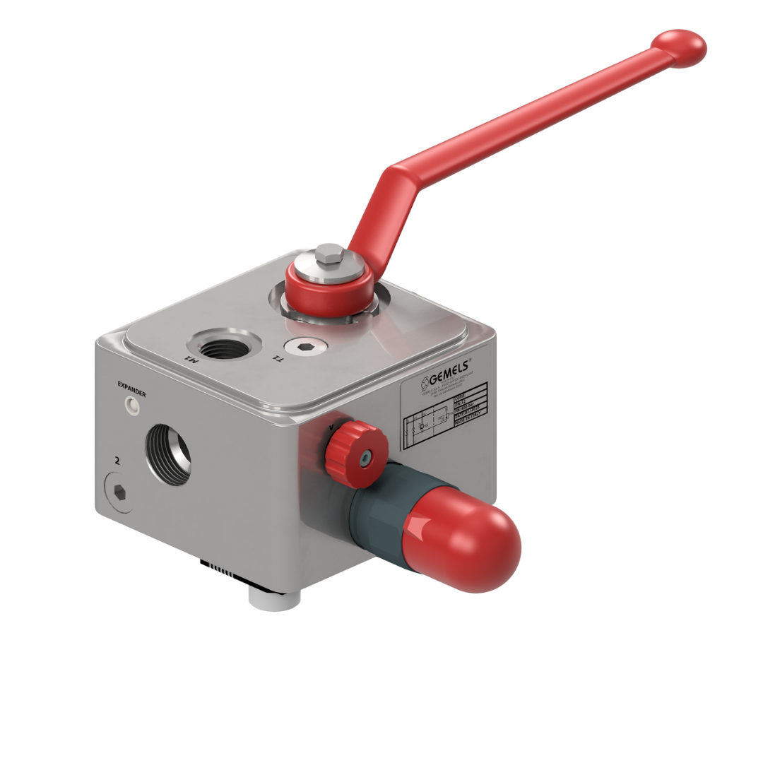
The safety valve is a hydraulic isolation and drainage block with safety functions designed for hydraulic accumulators. The block consists of at least three basic components.

  • The main valve is a ball valve (BV), responsible for intercepting and isolating the accumulator from the hydraulic system.
  • The safety component is an automatic safety valve (DBV), preset to the required pressure.
  • The manual drainage system is operated by a needle valve (V), which allows the fluid to drain.
  • An optional component is the solenoid valve (SV), which enables remote fluid drainage.

All models are equipped with a directly actuated safety valve, which drains the fluid in the event of an abnormal pressure increase. As a safety component, it is certified, calibrated and CE marked in accordance with the European Pressure Equipment Directive (PED) 2014/68/EU.

For safety reasons, it is essential to install the safety valve block as close as possible to the accumulators. The safety valve fully complies with all safety requirements set out in Annex I of the PED Directive 2014/68/EU.

General features

  • Temperature: -20°C + 90°C
  • Threads: BSP, NPT, SAE J1926
  • Material: Phosphated carbon steel
  • Fluid viscosity range: 10 – 40cSt
  • Available with solenoid valve power supply: 24VDC, 105VDC, 110V, 220V, P=18W
Technical Details
SAFETY VALVE MANUAL AND SOLENOID OPERATED
Item code Type DN INCH PN MPa A mm ⌀A mm ⌀A/QC mm B mm ⌀B mm B1 mm b mm C mm C-BSPP C RF mm C RTJ mm C1 mm Cavity L mm Cavity L1 mm C-D ch mm CH1 mm CS D mm D1 mm d mm ⌀d mm ØD mm ⌀d/QC mm E mm ⌀E mm ⌀E linea mm E1 mm E2 mm E3 mm E4 mm E5 mm E6 mm E7 mm E8 mm E9 mm ES.V mm F mm F1 mm Flow max l/min Flow min-max l/min G mm ⌀G mm ⌀G* mm G1 mm H mm ⌀H mm H1 mm I mm I1 mm ISO5211 J mm K mm ⌀K mm ⌀K* mm n°⌀K mm ⌀K1 mm L mm L1 mm L2 mm L3 mm L4 mm LSCH80 mm ⌀LW mm ⌀LW1 mm M mm ⌀M mm ØM1 mm N mm ⌀N mm O-ring P mm ⌀P mm Pilot Ratio Pressure cracking MPa Pressure max MPa Pressure max peak MPa Pressure max rotating MPa Pressure max static MPa Pressure max woking MPa Q mm ⌀Q mm R mm ⌀R mm ⌀RA mm S mm ⌀S mm Setting range MPa Setting standard MPa SW mm SW1 mm T mm ⌀T mm U mm V mm V1 - V2 C1 - C2GAS - MET W mm W* mm W1 mm W2 mm Weight kg X mm X* mm ⌀X mm X1 mm X-BSPP Y mm ⌀Y mm Y1 mm ⌀z mm
PG00305 10 42 59 117 99 125 193 110 117 10 G3/8 137 M33×2 9 G1/2
PG00331 10 42 59 117 99 125 193 110 117 10 N3/8 137 M33×2 9 N1/2
PG00332 10 42 59 117 99 125 193 110 117 10 SAE6 9/16-18 UNF 137 M33×2 9 SAE8 3/4-16 UNF
PG00306 20 42 74 144 119 108 182 200 121 20 G1 157 M33×2 14 G1/2
PG00333 20 42 74 144 119 108 182 200 121 20 N1 157 M33×2 14 N1/2
PG00334 20 42 74 144 119 108 182 200 121 20 SAE16 1-5/16-12 UNF 157 M33×2 14 SAE8 3/4-16 UNF
PG00351 25 42 87 152 129 119 187.5 200 132 25 G1 168 M33×2 14 G1/2
PG00352 25 42 87 152 129 119 187.5 200 132 25 N1 168 M33×2 14 N1/2
PG00353 25 42 87 152 129 119 187.5 200 132 25 SAE16 1-5/16-12 UNF 168 M33×2 14 SAE8 3/4-16 UNF
PG00307 32 42 99 158 129 119 187.5 200 165.5 32 G1 1/2 189 M33×2 17 G1/2
PG00335 32 42 99 158 129 119 187.5 200 165.5 32 N1 1/2 189 M33×2 17 N1/2
PG00336 32 42 99 158 129 119 187.5 200 165.5 32 SAE24 1-7/8-12 UNF 189 M33×2 17 SAE8 3/4-16 UNF
SAFETY VALVE MANUAL OPERATED
Item code Type DN INCH PN MPa A mm ⌀A mm ⌀A/QC mm B mm ⌀B mm B1 mm b mm C mm C-BSPP C RF mm C RTJ mm C1 mm Cavity L mm Cavity L1 mm C-D ch mm CH1 mm CS D mm D1 mm d mm ⌀d mm ØD mm ⌀d/QC mm E mm ⌀E mm ⌀E linea mm E1 mm E2 mm E3 mm E4 mm E5 mm E6 mm E7 mm E8 mm E9 mm ES.V mm F mm F1 mm Flow max l/min Flow min-max l/min G mm ⌀G mm ⌀G* mm G1 mm H mm ⌀H mm H1 mm I mm I1 mm ISO5211 J mm K mm ⌀K mm ⌀K* mm n°⌀K mm ⌀K1 mm L mm L1 mm L2 mm L3 mm L4 mm LSCH80 mm ⌀LW mm ⌀LW1 mm M mm ⌀M mm ØM1 mm N mm ⌀N mm O-ring P mm ⌀P mm Pilot Ratio Pressure cracking MPa Pressure max MPa Pressure max peak MPa Pressure max rotating MPa Pressure max static MPa Pressure max woking MPa Q mm ⌀Q mm R mm ⌀R mm ⌀RA mm S mm ⌀S mm Setting range MPa Setting standard MPa SW mm SW1 mm T mm ⌀T mm U mm V mm V1 - V2 C1 - C2GAS - MET W mm W* mm W1 mm W2 mm Weight kg X mm X* mm ⌀X mm X1 mm X-BSPP Y mm ⌀Y mm Y1 mm ⌀z mm
PG00296 10 42 59 117 99 125 193 110 108 10 G3/8 75 M33×2 9 G1/2
PG00325 10 42 59 117 99 125 193 110 108 10 N3/8 75 M33×2 9 N1/2
PG00326 10 42 59 117 99 125 193 110 108 10 SAE6 9/16-18 UNF 75 M33×2 9 SAE8 3/4-16 UNF
PG00297 20 42 74 144 119 108 182 200 121 20 G1 95 M33×2 14 G1/2
PG00327 20 42 74 144 119 108 182 200 121 20 N1 95 M33×2 14 N1/2
PG00328 20 42 74 144 119 108 182 200 121 20 SAE16 1-5/16-12 UNF 95 M33×2 14 SAE8 3/4-16 UNF
PG00344 25 42 87 152 129 119 187.5 200 132 25 G1 106 M33×2 14 G1/2
PG00350 25 42 87 152 129 119 187.5 200 132 25 N1 106 M33×2 14 N1/2
PG00298 32 42 99 158 129 119 187.5 200 165.5 32 G1 1/2 127 M33×2 17 G1/2
PG00329 32 42 99 158 129 119 187.5 200 165.5 32 N1 1/2 127 M33×2 17 N1/2
PG00330 32 42 99 158 129 119 187.5 200 165.5 32 SAE24 1-7/8-12 UNF 127 M33×2 17 SAE8 3/4-16 UNF
Certifications
valvole certificate CE
CE PED

The CE PED certification (Pressure Equipment Directive) regulates the design, manufacture, equipment and conformity assessment of pressure equipment ensuring a high level of safety in the EU.

Download: Catalogues and Drawings

SAFETY VALVE

DATASHEET
Solutions
Information Request

Request Information

Information Request

"*" indicates required fields

E-mail*
This site is protected by reCAPTCHA and the Privacy Policy and Terms of use from Google.
This field is for validation purposes and should be left unchanged.